The 3-4 axis hydraulic press brake machine has more control axes, suitable for more complex bending processing, and has high bending accuracy.
3+1 axis refers to controlling the up and down movement (2 axes) and operation of two oil cylinders in the system, as well as the forward and backward movement of backgauge (1 axis). The 4+1 axis adds an up and down movement positioning function of the backgauge system on the basis of the 3+1 axis.
1.The press brake machine uses international famous brand electro-hydraulic servo valves and scales to realize closed-loop control mode and ensure high-precision slider position feedback.
2.CNC press brake has precise and smooth operation, good synchronization performance, high bending accuracy, and high repetitive positioning accuracy of the slider.
3.According to the customer's demand, the rear blocking mechanism can adopt the rear blocking shaft material with better function.
4.Hydraulic system of press brake adopts integrated control system, which reduces pipeline installation, avoids oil leakage, ensures the working stability of the machine, and makes the appearance more scientific and beautiful.
5.The press brake machine is equipped with hydraulic deflection automatic compensation mechanism to eliminate the influence of slider deformation on the quality of workpiece, the CNC system automatically adjusts the compensation amount, easy and accurate operation.
|
Type |
Nominal pressure (KN) |
Workbench length (mm) |
Workbench width (mm) |
Poles distance (mm) |
Throat depth (mm) |
Main motor (kw) |
Dimensions L*W*H (mm) |
|
40*1600 |
400 |
1600 |
900 |
1165 |
350 |
5.5 |
2250*1650*2400 |
|
63*2500 |
630 |
2500 |
900 |
1960 |
380 |
5.5 |
3150*1700*2500 |
|
80*2500 |
800 |
2500 |
900 |
1960 |
380 |
7.5 |
3150*1700*2500 |
|
80*3200 |
800 |
3200 |
900 |
2760 |
380 |
7.5 |
3850*1700*2500 |
|
100*3200 |
1000 |
3200 |
950 |
2750 |
390 |
7.5 |
3900*1800*2650 |
|
125*3200 |
1250 |
3200 |
950 |
2750 |
390 |
11 |
3900*1800*2680 |
|
160*3200 |
1600 |
3200 |
1000 |
2740 |
400 |
15 |
4000*1900*2720 |
|
200*3200 |
2000 |
3200 |
1000 |
2730 |
400 |
18.5 |
4000*1900*2720 |
|
300*3200 |
3000 |
3200 |
1330 |
2720 |
500 |
22 |
4000*2200*3500 |
|
100*4000 |
1000 |
4000 |
950 |
3350 |
390 |
7.5 |
4800*1800*2650 |
|
125*4000 |
1250 |
4000 |
950 |
3350 |
390 |
11 |
4800*1800*2680 |
|
160*4000 |
1600 |
4000 |
1000 |
3340 |
400 |
15 |
4800*1900*2720 |
|
200*4000 |
2000 |
4000 |
1000 |
3330 |
400 |
18.5 |
4800*1900*2800 |
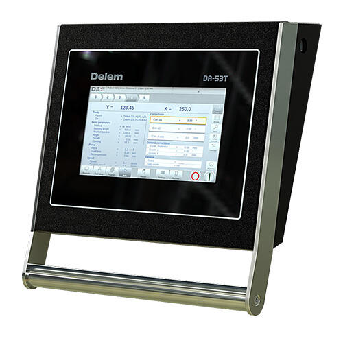
- CNC DELEM DA53T with 2D graphics and 3D visualisation
- Main Motor Siemens Germany brand
- INOVANCE Servo Motor (option)
- Pump First USA brand
- Hydraulic Valve BOSCH-REXROTH Germany brand
- Foot Pedal Italy Pizzato brand
- Grating Ruler GIVI Italy Brand
- Electrical Schneider France brand
- Ball Screw& Linear guide Hiwin Taiwan brand
- Fast Clamping
- Light Curtain KELI brand (option)
The machinery frame features a fully-welded and processed construction, with ANSYS finite element analysis employed for assessing the principal components of the frame, thereby guaranteeing the dependability of the machine and its overall accuracy. Each press brake is built upon a robust, one-piece foundation fabricated from premium-grade, high-strength steel, ensuring that our press brakes deliver consistent and trustworthy performance annually.


Dual hydraulic cylinders on either side of the ram provide faster approach speeds. Cylinders are synchronized to provide smooth motion, resulting in accurate ram positioning to within 0.004".
RAYMAX press brakes can easily handle parts with deep bends and long tooling due to their open space design. Our machines typically have deeper throat depths, greater daylight clearance and longer stroke lengths than most manufacturers on the market. We mount the RAM GUIDING on the outside of the frame to maximize the distance between the side frames to accommodate deep part flanges.


CNC crowning ensures a constant bend angle across the full length of the machine. This is achieved by pre loading the machine, to offset any possible deflection under load or compensate for any tool wear, so that under load contacting surfaces are parallel to each other.
With CNC crowning systems the press brake control is preprogrammed with machine characteristics and deflection data. With manual crowning a simple spread sheet or chart can be easily developed for each application.

Manual Crowning
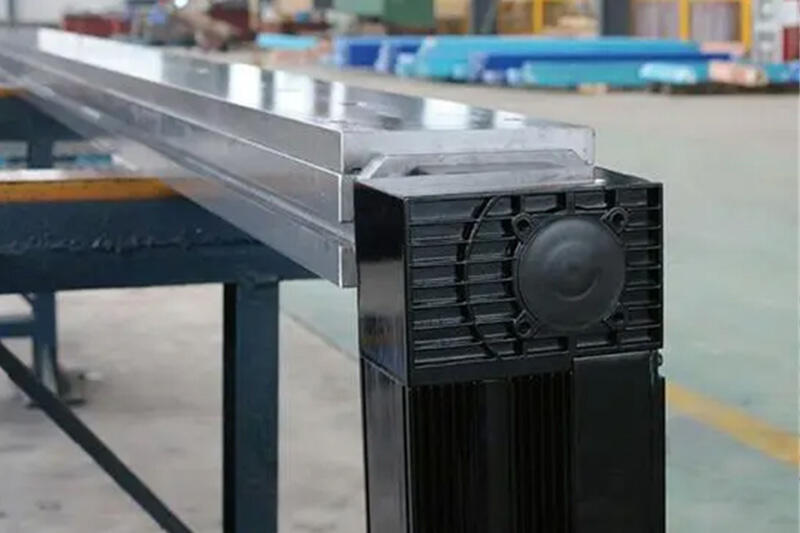
Deflection Compensation Workbench
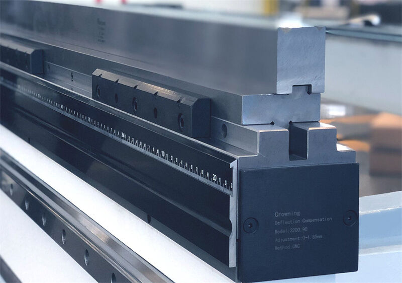
RAYMAX PPO Family CNC Crowning
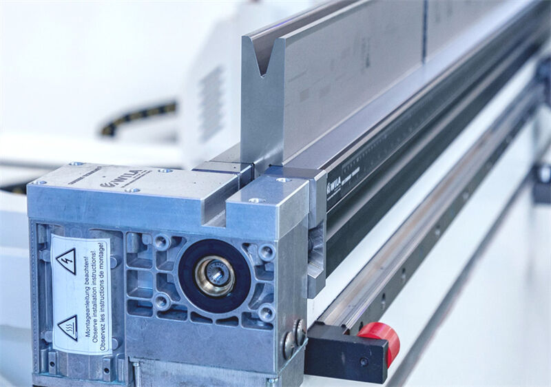
Wila Tool Holders And Crowning System

-10.1" high resolution colour TFT
-2D graphical touch screen programming
-“Hot-key” touch navigation
-Up to 4 axes (Y1,Y2 + 2 aux. axes)
-Profile-T offline software
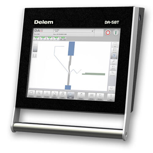
- 15" high resolution colour TFT
- 2D graphical touch screen programming
- Up to 4 axes (Y1, Y2 + 2 aux. axes)
- Bend sequence calculation
- Profile-58TL offline software
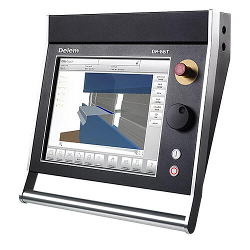
- 17" high resolution colour TFT
- 2D graphical touch screen programming mode
- 3D visualisation in simulation and production
- Profile-T2D offline software
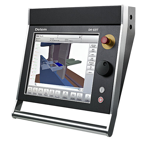
- 17" high resolution colour TFT
- 2D and 3D graphical touch screen programming mode
- 3D visualisation in simulation and production
- Profile-T3D offline software
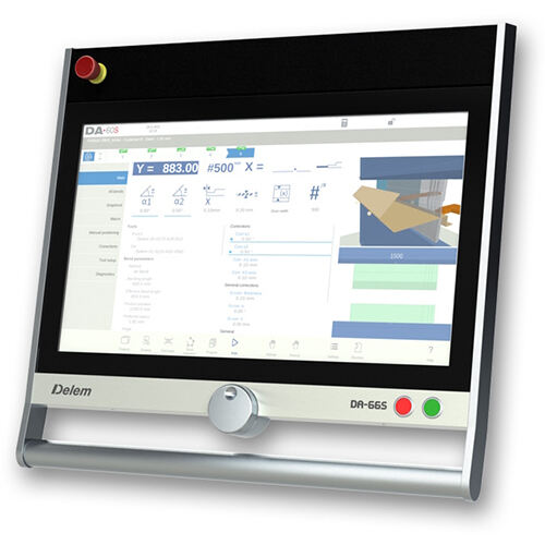
- 24" high resolution color TFT
- 2D graphical touch screen programming mode
- 3D machine representation, in simulation and production
- Profile-SL offline software
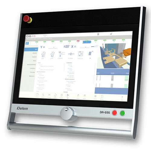
- 24" high resolution color TFT
- 3D and 2D graphical touch screen programming mode
- 3D visualization, including 3D machine representation, in simulation and production
- Profile-S3D offline software

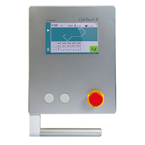
- 7” color graphic CRT screen
- 2D graphic profile creation with manual sequencing
- Up to 4 axes (Y1,Y2 + 2-axes)
- Angle and back gauge correction.
- Delivered with PC1200 offline software
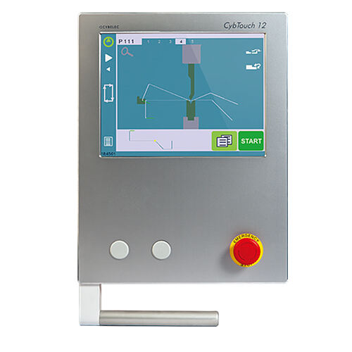
- 12” color graphic with fully touch screen
- Touch 2D graphic part creation with manual sequencing
- Up to 4 axes (Y1, Y2, X, R-axes)
- Angle and back gauge correction.
- Delivered with PC-ModEva offline software
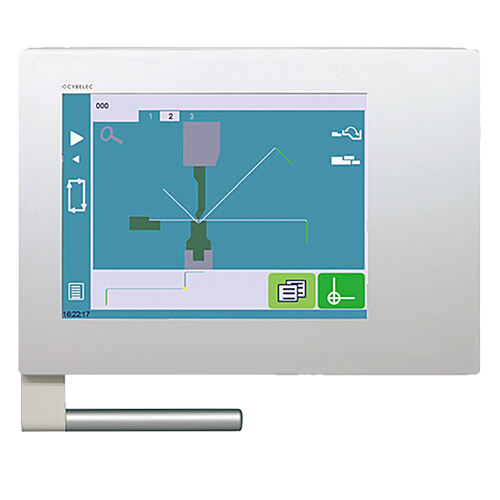
- 15” color graphic with fully touch screen
- Touch 2D graphical profile drawing and precise 2D program creation
- Up to 6 axes (Y1, Y2, X, R, Z1, Z2-axes)
- VisiTouch 2D or VisiTouch MX offline software.

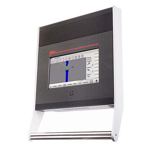
- 10 inch LCD touch screen (Resistive)
- Touch 2D graphic part creation with manual sequence
- Stander to 4 axis(Y1, Y2, X, R)
- Free off-line PC simulation software
- Tandem machine management (option)
- Modbus TCP interface for SCADA or MES (option)
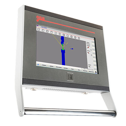
- 15 inch LCD touch screen (Resistive)
- Touch 2D graphic part creation with automatic sequence
- Stander to 4 axis, can up to 6 axis max.
- Free off-line PC simulation software
- Tandem machine management(option, can up to 4 machines)
- Modbus TCP interface for SCADA or MES (option)
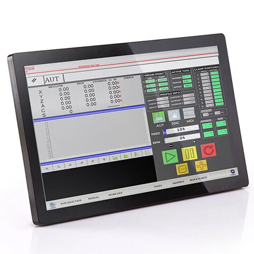
- 18.5" designed for multi touch screen
- Support import of tools shapes (.dxf ifles)
- Support ESA 3D Bend software
- Equip standard industry 4.0 Modbus TCP interface
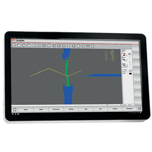
- 21.5” designed for multi touch screen
- Support multi touch application
- Support import of tools shapes (.dxf files)
- Support ESA 3D Bend software
- Equip standard industry 4.0 Modbus TCP interface

RAYMAX offer 2, 4 and 6 axes support brackets to help with all your bending needs. Let us help you configure the best solution for your press brake needs.

BGA-2 BackGauge(X,R)
- Ball screws and linear guide on X, R-axis
- Axis X speed 500 mm/s.- Manual Z1, Z2-axis with HIWIN linear guide
- Mechanical accuracy ± 0.03 mm.
- Fingers with double stop and micrometric adjustment.

BGA-4 BackGauge(X,R,Z1,Z2)
- Ball screws and linear guide on X, R-axis
- Precision belts and YYC rack on axes Z1-Z2.
- Fingers with double stop and micrometric adjustment.
- Mechanical accuracy ± 0.03 mm.
- Axes Z1-Z2 speed 1000 mm/s.
- Axis X speed 500 mm/s.
BGA-6 BackGauge(X1, X2, R1, R2, Z1, Z2)


1.Rolleri Clamping System
The new clamping Amada, Boschert, Bystronic-Beyeler Euro-B, ROL200 for Punches! Compatible with: NEWDurmazlar, Ermaksan, Gasparini, Haco, Promecam, etc. The new patented system enables manual, pneumatic or hydraulic vertical clamping of your top tools. The special features are the enormously simple handling and the surprisingly low price, which guarantees huge efficiency.Advantage:
- Fast vertical tool change for all Rolleri R1 type punches2.Wilson Pneumatic Clamping
This innovative fast clamping system can satisfy any needs, the Express Air clamping reduces press brake setup time and therefore it represents the best choice for users that frequently change punches on their press brakes for sale.
Advantage:
- Fast vertical tool change for all Europe type punches
- Safe and fast tool change
- Substantial improvement in time consumption and related costs
- Secure against tool falling down
- Available in manual, pneumatic and hydraulic models


3.Wila Hydraulic Clamping System
The Wila’s ‘New Standard’ Tooling System has become market leader for precision, quality and flexibility for the RAYMAX hydraulic press brakes for sale.
Advantage:
- Long service life: >10 years
- Quick clamping for WILA style tooling
- Simple push-button loading
- Fast and safe tool changes: Reduce 80% time
- High-precision bending angle and flange edge

The hydraulic press brakes with Sheet supports follower system for bending long and thin sheets. It basically consists of a pair of sheet supports placed on the front of the machine at the height of the bending line (bottom tool). Supports are controlled by the CNC, following and supporting the sheet during the bending process.
Reverse bending occurs when we bend a very large, heavy and thin plate. The overhang generates a torque that makes the sheet bend around the die edge under its own weight, as we can see in the drawing. The sheet lifter helps to avoid this type of damage, supporting the plate during the entire bending cycle.
Advantage:
- Automatic bending follower supports
- AP1-AP2 CNC-controlled interpolated axes
- Recommended for heavy parts or large thin plate
- Bend as closed as 70°
- Load capacity-180 kg per support
- Brush and support shaft dim 350x900 up to 1200 mm
Hybrid Servo Motor
- 30% energy saving
- High efficiency
- Environmental protection and no pollution
- Low fuel consumption
- Low maintenance and use cost
- Good sealing performance

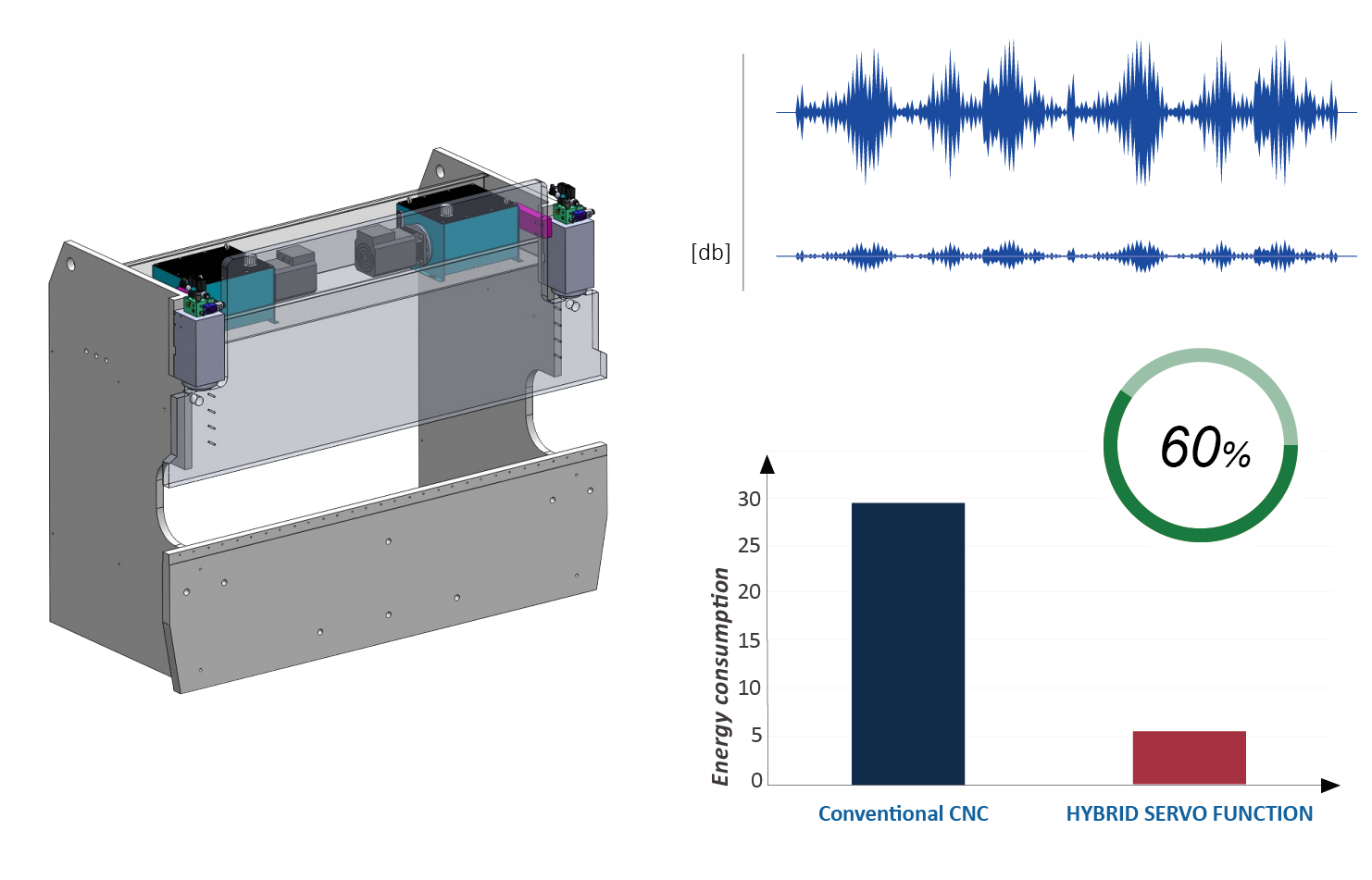
Hybrid Plus Servo Motor
- Saving: 60% electricity savings compared to conventional drives.
- Efficient: High up to 30%, more efficient (reduced cycle time).
- Accurate: More accurate positioning, up to 5um
- Quiet: Quieter of machine operation due to reduced noise
- Less: Hydraulic oil use is minimal, only 30% compared to conventional ones
- Easy: Easier to build, easier to maintain and lower failure rate of the machine.

DSP laser safety protection device comprehensively protects the personal safety of bending machine operators and avoids danger due to the rapid movement of the slider on the machine. A block-shaped protection area is formed for the bending tool tip to protect the front, middle and rear areas of the tool tip. The protective zone is fixed under the tool tip and moves synchronously with the tooling, ensuring that any object underneath the tooling at high speed must first enter the protective zone created by the DSP before it touches the tool tip. Once an obstruction (such as a worker's finger) enters the DSP protection zone, the DSP will immediately send a signal and interrupt the downward movement of the slider.